
Operating System Design :: Lessons :: Boolean Logic
Boolean Algebra
This lesson is a synopsis of Chapter 1 from the book Building a Modern Computer From First Principles. After reading this synopsis you should read that chapter as well as Appendix A that describes the Hardware Description Language. Boolean values, sometimes called binary values, are typically labeled true/false, 1/0, yes/no, on/off, and so forth. The simplest way to specify a boolean function is by using a truth table that specifies that function's outputs based on its inputs. Below is an example truth table for the Boolean function (x + y) • x̄ where x̄ means NOT x.
| x | y | z | f(x, y, z) |
|---|---|---|---|
| 0 | 0 | 0 | 0 |
| 0 | 0 | 1 | 0 |
| 0 | 1 | 0 | 1 |
| 0 | 1 | 1 | 0 |
| 1 | 0 | 0 | 1 |
| 1 | 0 | 1 | 0 |
| 1 | 1 | 0 | 1 |
| 1 | 1 | 1 | 0 |
Every Boolean function can be expressed using And, Or, and Not. Below are all the possible Boolean function using two variables.
| x | 0 | 0 | 1 | 1 | |
|---|---|---|---|---|---|
| Function | y | 0 | 1 | 0 | 1 |
| Constant 0 | 0 | 0 | 0 | 0 | 0 |
| And | x • y | 0 | 0 | 0 | 1 |
| x And Not y | x • ȳ | 0 | 0 | 1 | 0 |
| x | x | 0 | 0 | 1 | 1 |
| Not x And y | x̄ • y | 0 | 1 | 0 | 0 |
| y | y | 0 | 1 | 0 | 1 |
| Xor | x • ȳ + x̄ • y | 0 | 1 | 1 | 0 |
| Or | x + y | 0 | 1 | 1 | 1 |
| Nor | x + y | 1 | 0 | 0 | 0 |
| Equivalence | x • y + x̄ • ȳ | 1 | 0 | 0 | 1 |
| Not y | ȳ | 1 | 0 | 1 | 0 |
| If y then x | x + ȳ | 1 | 0 | 1 | 1 |
| Not x | x̄ | 1 | 1 | 0 | 0 |
| If x then y | x̄ + y | 1 | 1 | 0 | 1 |
| Nand | x • y | 1 | 1 | 1 | 0 |
| Constant 1 | 1 | 1 | 1 | 1 | 1 |
Gate Logic
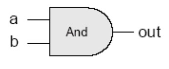
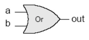
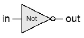
A gate is a physical device that implements a Boolean function. Today's computers rely on electricity to implement gates with chips that are transistors etched in silicon. There are three primitive gates that can be used to construct composite gates. The three primitive gates are And, Or, and Not.
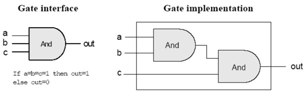
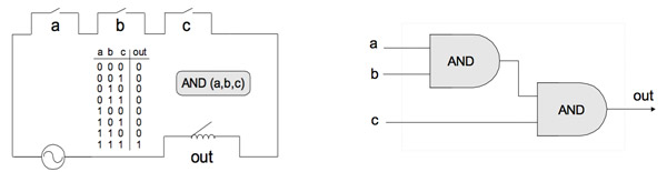
Composite gates are gates made up of primitive gates. The example below represents the function if (a=b=c=1) then out = 1. The interface of a gate only shows its inputs and outputs while the implementation of a gate shows the primitive gates the composite gate is composed of.
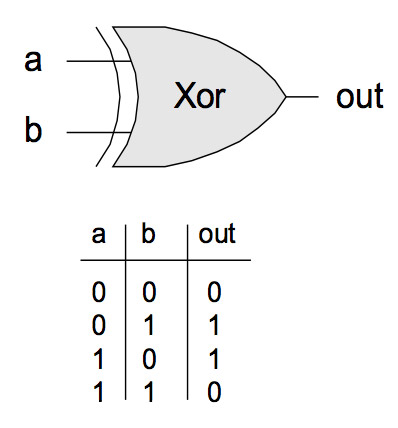
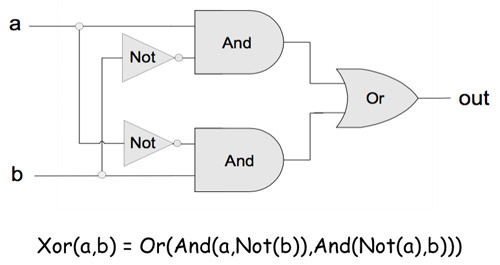
An Xor gate takes two inputs and outputs 1 if exactly one of the inputs is 1. Below is the interface and implementation of an Xor gate. A gate's interface is unique, meaning that there is only one way to describe it using a truth table. However, different implementations can be used to realize an interface. Some implementation are better than others in terms of speed, cost, and simplicity. In general, it is best to use as few primitive gates as possible to implement a composite gate.
Circuit Implementation
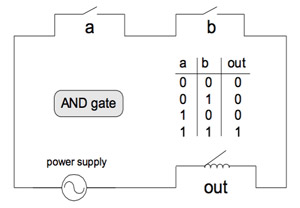
You can easily construct working gates yourself with some silicon, transistors, copper wire, and a soldering iron. You can see the structure of an And Gate in the electrical diagram below. Electricity can only flow through the wire if the transistors at inputs A and B are both "open" or at a high voltage level.
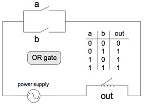
An Or Gate has a different diagram that allows electrical flow if either of the input gates are "open."
Below is an electrical diagram of the 3-input And Gate we saw earlier.
Hardware Description Language
A Hardware Description Language or HDL is language used for modeling hardware. A tool called a hardware simulator take an HDL program as input and builds an image of the working chip in memory. The outputs of that chip can then be inspected to determine if they produce the desired results. Hardware simulators are usually designed to run test scripts that are written in a scripting language. These test scripts act like unit tests to determine if the chip behaves as expected.
The hardware simulator that will be used in this course can be downloaded here. You can follow the steps on the website to run the software. You can see a tutorial of the hardware simulator here.


